Role of Architects in Intelligent Building emerging in the new era of the construction industry

Overview

Architects play an important role in new construction and renovation of building or old structures. An architect develops the facility program of building owner and assembles the design team who contributes to the success of the project.

An architect designs the smart building and indicates how the process would be to carry out the aesthetics of a smart building. They understand how important it is to monitor, control, and automate systems to build a smart building. All these systems contribute to a facet of the building that adjusts to the building’s environment and operational performance to look into safety measures, comfort, sustainability, and healthy atmosphere.

Smart buildings or intelligent building does not only depend on control and automate systems; it heavenly depends upon fixed attributes of the buildings such as initial siting, the structure, windows and interior layout in how buildings would operate and functions.

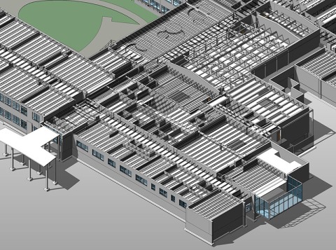
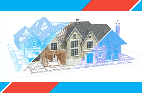
An intelligent building is designed in a way that depicts the present and future needs of occupants living in it and enhances knowledge and how designers or planners use its intelligence. Architectural BIM Services helps the designers to perform complete design in detail by using BIM Model for representation purpose of showing clients how the building will look like once built in real and about object placements.

Facility Programming

Development of a facility program is done by an architect in collaboration with engineers, consultants, facility programmers, and manufacturers. Designing intelligent building is a creative and iterative process where the owner’s objective, values, and preferences and the need for aesthetics, economic, energy analysis, and sustainability.

Few features of the facility program will be soon mandated by government intervention, among which one is the LEED certification program. Smart Building Institute (SBI) will give certificate based on advanced technology, system and data integration, building operations which describe the detailed framework and properties of the intelligent building.

Design Teams

Facility program is transformed into a detailed design where the team determines the design requirement, specifies and draws up the project, produces the construction document, and administers the construction contract.

For constructing a smart building, it is necessary that the architects must select appropriate design team that is creative, innovative, technology saved and experienced. Designers must be upgraded to make buildings as per standards and keeping in mind the environment, and the architect must know how to deal with complex buildings.

Siting the Building

Architects in today’s era are helping the owner’s in selecting and venturing new site for construction purposes or existing building survey. Selecting a site is a very important aspect of the smart building as the design will be affected by the specification of a site, topography, climate, and public utilities.

Materials

Architects and design team inspects about what materials will be used in the building. Materials do deteriorate and wear out and often results in condensation, corrosion, stains, fungus, and other negative properties. It affects the ongoing cost and ease of maintenance, repairing, and replacing services. Selection of material must think of utilizing the long-term use and cost of the materials and minimize the maintenance through standard products.

Conclusion

The intelligent building does contribute to the design concept and impacts the level of efficiency to suit the needs of occupants. Architects and BIM Services Modelers must update themselves regularly to standards, designs, regulation, and policies. The material must be carefully read and understood to implement the construction of smart buildings. It has to mainly look forward to sustainable and energy analysis of the building.

Precise difference between Construction Drawings and Shop Drawings

Overview

An influx of drawings is overflowing the AEC Industry to counterpart diagrams used at every stage of project life-cycle from conceptual design to construction. In the world of virtual design and construction, construction drawings and shop drawings are an essential part and are invaluable to building projects. These drawings are implemented on the design stage itself.

Let’s have a glance at a subtle difference between both the drawings:

Construction drawings

Architectural Construction Documents also known as working drawings are those drawings that are prepared by designers and architects to visualize the architectural components placed in building or structure before the construction process begins. It includes all the specification of the architectural components and is both written and graphically presented to take decisions in the Design stage. These Drawings are considered as the life of any construction project.

Construction drawings are the exact and accurate graphical representation of what will be constructed. They consist of all the revisions from start to end. Changes or modification is done in the original diagram itself. Drawings must be made according to government regulatory authorities for approval sanction. It includes specifications of materials and techniques to be used as per standards that need to grab the details of construction as a whole. These drawings are drawn to scale and often drawn by hand earlier, but now it’s prepared with the help of 3D design software through CAD. It includes drawings about elevations, sections and more. With the advent of BIM, it can be built using Virtual Construction Modeling that provides contractors with exact scaled drawings.

CDvsSD

Shop Drawings

Shop drawing relates to details about components of the building such as what kind of materials will be required for the components, dimensions of proposed installations and timeline to finish the fabrication of components. Contractors, suppliers, and fabricators generally prepare it. It depicts the drawings related to pre-fabricated components on how they will be manufactured and installed. It takes design intent drawings and specifications prepared by the design team to show how the components will be manufactured, assembled and installed. It is made before the actual construction process begins, eliminating errors at the design stage itself. It primarily focuses on MEP Components and provides details about MEP Shop Drawing Services. These drawings are the initial plan of the project and are used to start the pre-fabrication process of the components, to save time while rest design is being worked upon. These drawings are more detailed than the construction drawings. It includes drawings about beams, elevators, trusses and more that can be set in the design stage itself and later be pre-fabricated. It helps in clash detection of components and can be resolved during the design stage.

Conclusion

BIM Integration in construction and shop drawings is transforming the construction process. Both drawings are vital for construction professionals and can be implemented by looking upon its pros and cons. Architects prepare working drawings that help them to represent the components and communicate them to end clients. Whereas shop drawings are used by fabricators to know how the components will be manufactured and installed during the construction process.

Benefits of Outsourcing Structural Steel Detailing Services

Overview

Structural Steel Detailing is a vital process of structural engineering and needs accuracy to be attained. It is an important and mandatory process in the construction field. It provides a communication link between architects, engineers, contractors, fabricators, and others for maintaining accuracy at each stage.

It is necessary to outsource steel detailing services to expertize companies in turn to depict CAD Drafting Services that are essential and needs ideally.

Importance of Structural Steel Detailing Services

Structural Steel Detailing Services leverages many benefits out of which the most common is that 2D drawing print can be shown as mock-up first to the client and any changes made in the plan can be curated and applied after which 3D Rendered Drawing can be taken out. It enhances the ability to get feedback and communicate easily with the clients to make the work process smoother.

Benefits of Structural Steel Detailing Services

Quality Drawings: – Steel detailing services needs in-depth drawings in the form of 2D or 3D which is done for Residential, industrial buildings, bridges and more. Coordinating with skilled and experienced engineers will ensure that you are getting the best quality in return. The drawing would be accurate and understandable by the contractors, and they would, in turn, know what needs to be done. So with this, a walkthrough model can be prepared to understand what output will be built.

Time-Saving: – Drawings here require accuracy which incurs a lot of time. Creating various drawing and details is difficult at times and time-consuming. If you do it in-house would be investing time and labor to conduct work. So by outsourcing this, you can put your team in other projects and increase optimum productivity and take larger projects.

Cost Saving: – If you are willing to outsource, you will indeed save cost on investment in CAD Software and hiring labors. Periodically an employee needs to be hired for working on drawings so that can be eliminated if you outsource. Without comprising on budget, the requirements will be fulfilled.

Better Reporting: – When you use CAD Software and outsource these services, you get major benefit of better reporting. The software creates various reports that include a report about materials summaries, gather sheets, and more. It will ensure that everyone is working within the same platform and ensures timely reports are generated. Even fabricators would know what exactly they need to create and the financers would estimate exact budgeting solution accordingly.

Convenient Information: – Tekla usage can be determined by outsourcing the information which can be accessed from anywhere. Larger files can be transferred easily without any hindrances and can be saved in drop box maintaining its security.

Quality Tools: – Drawings can be integrated from various systems that can be used by fabrications and facility managers once the project gets accomplished. With the advancement in technology in use, you will get superior results. You can avail the benefit of getting more quality tools.

Conclusion

By outsourcing Structural Steel Detailing Services, you get to avail major benefits and fewer burdens. You save a lot of time and money incurred behind the labor hiring and software installation. Better quality and all the requirements of yours get full-fledged. Timely delivery and optimum productivity can be attained through expertize team outsourced.b m

Structural Steel Analysis – An important part of Structural Engineering Services

The Structural Detailing Services or steel analysis process provides a range of benefits to the structural engineers along with contractors, engineers, subcontractors and other professionals. The steel analysis process is performed by calculating mechanical stress along with calculation to related deformations and strains.

The structural steel analysis process has extensive usage is construction, structural engineering, civil engineering, automobile, aerospace, manufacturing, healthcare, etc. industries. Nowadays, the entire analysis process is carried out by using structural analysis software that produces better result than the manual steel analysis process. Calculations related to stress analysis helps to understand stress and strain levels pertain to building structures as well as other types of steel structures in an efficient manner.

Different features of Structural Analysis Process

  • Load analysis
  • Strain and stress analysis
  • Thermal stresses
  • Electrical forces
  • Magnetic forces

Purpose of Structural Steel Analysis

The prime purpose of structural analysis is to ideate whether elements or their assembled parts will behave properly or not. Numerous techniques such as computational simulation, testing, etc. are used for performing analysis for getting precise results. The units used for measuring stress, loads, etc. are in gigapascals, megapascals, pounds per square inch, and k pounds-force per square inch.

How to do Structural Analysis?

The important part of structural stress analysis consists of load analysis. Load analysis is performed for different types of loads such as amalgamation, torsion, tension, trim, density, etc. By performing load analysis, professionals can understand how much load will be tolerated by the structure or its associated equipments as well as parts. Another important part of structural analysis is fatigue analysis. It is very important to determine the effect of stress on the structural aerodynamic system.

Hence, structural analysis is very important for developing an error-free and stable structure. It is also very important to carry out this analysis process very carefully otherwise it can affect the performance of the structure badly in future.

Tesla outsourcing services based  on professional CAD and BIM Services provider providing high-end Structural Engineering Services to the AEC firms based in Australia.


The Synopsis of MEP Design Services and its Implication in Building Projects

MEP BIM Services have turn out to be an integral element of engineering design services. To produce mechanical components appropriately, we must undergo through the divers stages of MEP design development. Mechanical design is the most critical stage of design development procedure. Earlier at this stage, engineers draw the concept roughly and hand it over to the drafters and modelers to make systematic drawings and models out of those rough drawings.

Design of MEP has been produced with the assistance of CAD systems, which has replaced the manually drawing development approach significantly. Designs attained via CAD systems are comparatively very fine and clear, which also consume less time while development. It enables drafters to go by trial and error approach to find out the most suitable design without taking so much time.   Hence, CAD systems are highly preferred when it comes to developing diversified visuals and drawings

At Conceptual product designing stage, drafters garner the necessary details from clients and immerse them with their insight of how to achieve accurate designs as per client mentioned. Designers sketch out his/her ideas with the help of CAD software’s and give it appropriate colors on the models in order to make it seem as real as possible.

Once the models are created they are provided to the engineers for reviewing them. In this stage, the models are scrutinized systematically so that they don’t left with any errors. If engineers working on those projects identify any error they draw the attention of the modelers and drafters to rectify it and finally absolutely error free models are attained.

For more information about MEP CAD Services visit our website.

BIM Modeling Services are Great Tools to Organize Construction Remarkably

Building Information Modeling services are connected from the core to Architecture, Engineering and Construction industry individuals and these services enhance their working while development of the building.

Building Information Modeling services are applied for creating 3D models of architecture, structure and MEP systems, which are capable of containing immense degree of details in them.

Architectural BIM services, structural BIM services and MEP BIM Services together represent the information pertaining to design, construction, operations, and scheduling to the professionals working on the project.

The information regarding design, construction, operations, time and cost of the project is very crucial for the professionals as they can efficiently organize the onsite construction. The BIM Modeling Services can be optimized to examine the design and the design complication can be put to an end.   For instance, clash detection services is a brilliant alternative to detect clash into systems and by this the design quality of architectural, structural and MEP disciplines can be drastically enhanced.

Consequently the onsite work does not hinder by the occurrence of errors which reduces the efforts of fabricators and reduces the cost of project. Simultaneously, this also grants the contractor with time saving and ultimately the project can be handover the clients on the provided time.

4D Building Information Modeling is also quite useful alternatives for each and every building stakeholder connected to the AEC industry. 4D BIM is the most effective building modeling system when it comes to plan out effective schedule for building construction. At the same time, 5D BIM models are capable of representing project cost very accurately.

Why BIM is Preferred More over CAD by Construction Professionals?

The inception of building information modeling technology has notably changed the way of design development of a building project. In recent years, many architectural, engineering and construction (AEC) firms have shifted to BIM from CAD. The BIM designs are more useful and advantageous than any hand sketch or flat 2D CAD drawings. The Building Information Modeling has enabled the design and construction professionals to develop a digital database in 3D space for a building project. Though CAD also helps the users to develop 3D model but a CAD model does not provide and design related information of the building.

bim-modeling

The Revit BIM Services techniques assists the modelers to create a lifelike building model in 3D platform. This process enables the users to get an end to end visualization of the building from all possible angles. A 3D BIM Model also helps the users to view and understand all the elements of architectural, structural and MEP disciplines. Hence this model assists the professionals to discover clashes as well as interferences among the elements of different disciplines. So, BIM helps to save project costs and delays in a significant manner. CAD does not allow users to develop 3D BIM Coordination Services Model and discover clashes as well as interferences among the elements of the building.

Revit, BIM software, helps the designers and modelers to make any type of building information model photorealistic by applying appropriate color, texture, shadow effect and light effect. The photo-realistic design of a building project helps clients to get an idea of how the building will be appeared in real life.

BIM also facilitates collaborative design approach that helps the project team members to work simultaneously on a single piece of design in an efficient manner. CAD does not provide such type of facility. BIM also assists the users to add additional dimensions (i.e. time, cost, etc.) to the 3D model, where in a 3D CAD model, users can not add additional dimensions further.

Above are the reasons that the design and construction professionals prefer BIM more over CAD.

When, Where and How Family Content Creation is Required?

Revit families and content are created from 2D drawings or even from sketches by engineers for any construction project. Revit Family Creation Services is very important part of construction project as they are incorporated in developing 3D models. Families can be described as important building elements which are crucial part of multidiscipline models. Families are components use to build model, such as walls, windows, stairs, doors, etc.  Each family can have multiple types such as different size, materials, parameter variables, etc.  Any change in a Revit family is updated at every instance throughout the project. By creating our own content, we can more easily meet specific design criteria and reduce repetitive tasks.

stair-case-family

Revit family editor is one of the most important and efficient tool to create Revit families. With the Family type tool in Family editor new family types for developing families are created. The dimension tool add permanent dimension to the family. Revit automatically provides or assigns dimensions to the families as Revit users start drawing its geometry. These dimensions can be easily altered and changed by designers and modelers according to their project necessity with the assistance of dimension tool.

By including content with specified design and engineering properties, architects and engineers can quickly perform analysis on multiple design iterations and compare their aesthetics, performance and sustainability. This practice saves architects and engineers time for creating specific family content.

Revit Family Editor provides a means to create custom or manufacturer specific content. The architects and engineers do not always possess the necessary skills or more importantly the time to create this content on their own. With Revit BIM Services adoption growing worldwide, there has become more and more content available on the web from a variety of resources or from others users sharing content which they have created. Even with so much content already created and available there is still a demand from the Architectural, Engineering and Construction industry to supply their own products in a Revit format. Revit has predefined family templates in its library that are selected by users as per their project requirements.

There are various tools in family editor like Model Text tool, Control tool, Masking Region tool, Void Forms tool, and Load into Project tool etc for family content creation. By using predefined families and creating new ones in Revit both standard and custom elements can be added to building models.

Revit MEP – Eased the task of Developing MEP System in a Building

Revit MEP has contributed to alleviate the tedious and complex task of design and development of MEP systems in a building. These systems can be effective modeled and coordinated in Revit.

A number of systems in coherence form a completely functional building or facility. There are the civil aspects, then the structure and architecture of the building and the MEP and F disciplines that is the mechanical, electrical, plumbing and fire-fighting. All these systems have to be designed and developed in sync to ensure a properly operational facility.

Revit MEP - eased the task of developing MEP System in a Building

The structure and architecture form the base while translating the owner’s vision into a tangible design. As this is finalized, the MEP systems are designed into them. While coordination among all disciplines is extremely vital, it is the designing and coordination of the MEP portion that becomes slightly trickier. To effectively have the systems placed in the little space assigned for them in the overall design of the building makes it easier said than done.

Technology has advanced today to such lengths that we now have ‘super’ tools to aid us accomplish any task of any complexity. Revit MEP is such a ‘super’ tool for designing and modeling of MEP systems. Revit MEP Services work as a boon for the MEP engineers.

If we look back in time, before the advent of Revit and BIM Services, designing such complex systems was one cumbersome and weighty task. All the calculations and designing had to be executed manually. The drawings were all drafted by hand on paper. Later on, they began to be drafted on computer using AutoCAD 2D software. Either way, developing designs in such 2D formats were quite challenging.

There is the HVAC system, then the wiring system and the plumbing system – designing each of them and managing their technicalities while ensuring coordination between them can certainly be highly demanding tasks. These lengthy procedures were however followed to meet the requirements.

Then as the 3D modes came, it became easier to design and analyze and more so after the advent of parametric 3D modeling applications such as Revit arrived the scene. The lengthy, intricate tasks could be achieved fairly easily. Revit MEP has eased the burden to quite an extent of the MEP personnel. Certainly the task of designing and developing stay in the dexterous hands of the engineers, it is the platform that it is carried out on that contributes to lessening the efforts and time and also encouraging more creativity.

In MEP BIM Modeling services, the individual disciplines are designed and modeled and thereafter synced to ensure that there are no clashes among any elements. An accurate MEP system can be comfortably devised on Revit. The drawings for installation are also readily extracted from the model, after the finalisation of the coordination among all involved disciplines in the building.

Construction Drawings Précis

Working Drawings are a gateway from the design to the final physical building. These drawings constitute the working drawings that demonstrate what is to be constructed and how it looks. These drawings go together with a set of documents that include the specifications as to the materials to be used, the techniques for installation, standards in terms of quality that is to be maintained, etc. The drawings may have key information covered of the details in the specification documents.

Typically the scale that is used to draw is ¼” per foot, that is one forth of an inch in the drawing is equal to one foot in real. Correspondingly one inch would be 4 feet and so on. The architects and engineers use a specialized ruler that helps to easily translate the dimensions on the drawings.

There are various standardized symbols that are used in the construction drawings. These enable others in the trade to easily comprehend the meaning of any line or arrow or any symbol in the drawing. These symbols together present a meticulous guide as to how the building in concern comes together.

The drawings constitute the following:

Floor Plans: These drawings give the view of the structure directly from the top. They depict horizontal dimensions of the rooms, kitchens etc, with position of doors and other interior constituents. There are plans for all trades involved. There is a site plan, floor plan, electrical plan and so on.

Exterior elevations:These drawings show the view in a straight line from the side. They give vertical dimensions. It is to be noted that these are two dimensional drawings and so things appear to be in the same plane. For instance a sloped roof would appear flat and two walls at 10 feet distance would seem to be on the same plane. The information on the depth is not given. 3D Floor Plan Services are to be referred for it. Thus every drawing is key.

Sections:These show the inside of elements (walls, floors, etc.) as it is cut through the structure.

Details:These drawings are of certain elements that require further information which cannot be covered or made visible in the large drawings. They are typically for walls, stairs, windows, etc. There is a demarcation in the plan and elevation near the element whose detail drawing has been provided.The construction drawing services compile the entire set to enable construction of the building.